The difference between PCBA processing maintenance and soldering:the key to removing components from the circuit board is that all pin solders need to melt at the same time. The common maintenance and desoldering method is to use a heat gun to heat all the pins of the components at the same time, and then complete the desoldering. But for wide-body components, just using soldering iron plus solder is not enough to heat all the pins at the same time, so we can use heat-conducting copper wire, which can widen the tip of the soldering iron.
Use heat-conduction copper wire to desolder the Mini USB socket
The processing for removing the Mini USB socket is shown below. There requires heating the pins of the USB socket from three sides.

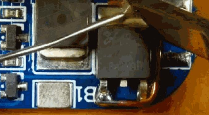
Use heat-conduction copper wire to desolder the power MOS tube
For this kind of power MOS tube, the same purpose can also be achieved by using heat-conducting copper wire.

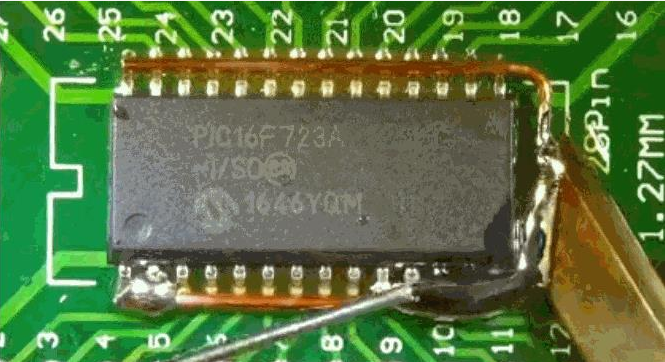
For larger SOP chips, use longer heat-conducting copper wire
What about wider components? Just use the longer heat-conducting copper wire. Of course, in addition to the heat-conducting copper wire, it is also necessary to apply more solder paste.

Use a soldering iron to heat the heat-conducting copper wire to melt the solder pins of the IC
The removal process is a struggle between the heat from the soldering iron and the heat from the board. If the power of the soldering iron is small, the heating process time will be very long. So using a high powered soldering iron will help shorten the removal process.
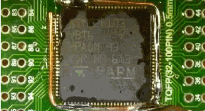
For TQFP100 chip desoldering
With a high-power soldering iron, no matter how large, the chip removal is not a problem.

Patiently heated, and finally removed the TQPF chip.
Add heat-conducting copper wires around, and then use solder to add a molten tin apron to the component, and finally the component will leave the circuit board.
Only by mastering desoldering can we cope with the soldering of any difficult devices.

More PCB Articles:
1.PCBA soldering requirements for PCB boards
2.SMT Processing Requirements For PCB Design Component Layout
3.The Processing Flow Of SMT Materials
