Before explaining how to perform function test after PCB Assembly, it is good to understand how it has been performed in the past. Well, the best way to learn about the actual testing is to visit a PCBA SMT Factory that makes similar products and see the entire production line, from the circuit board to the workshop until the product is packed and shipped. The secret is that we can actually experience the various processes of the product during production, which is very helpful for us to understand how the board is made.

PCBA Function Test Process
1. Function Test Plan
Before SMT Assembly of the printed circuit board, there is usually a DFM manual in the design process. This will allow you to participate in the timing of testability design throughout the design process. It will clearly indicate which test aspects are included in the schematic, PCB layout, and even microcontroller code.
For example, if the user touches a capacitive touch screen, what do you want that operation to do? Maybe it wakes up the screen or turns on the LED and tells the microcontroller to do something. This operation requires that all your components have the correct voltage, capacitive touch sensors and leds are installed correctly, and that the microcontroller is programmed and operated as expected. This functional test program will guide the entire circuit board fabrication process with significant assurance of quality.
2. Test Points
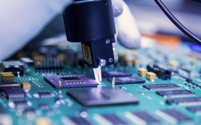
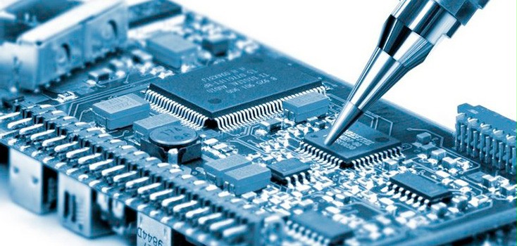
The test point is just the PCB pad on the circuit board, which is designed for easy detection. For a variety of reasons, you do not want to rely on probing the pins or pads of components. The dimensions of these pads are not specified but should be large enough to allow contact with the test probe.

3. System Programming
If you look at the internals of any sufficiently complex product, you may find a programming connector or an empty spot on the PCB where you can place the programming connector. This connector is typically used to program microcontrollers already installed on the PCB and is therefore referred to as “in system”. In a mass production, it would not make sense to install this header. It is used by designers for debugging purposes rather than being installed during production to eliminate costs.
4. Test Fixture
For early prototypes or small-scale designs, you can manually test each board yourself. You will thank your future self for completing this exercise because it enables you to appreciate and understand how to make sure your product works. Humans generally aren’t good at repetition, so having a test plan, even with checkboxes, can help you avoid skipping any steps.
In Grande, we will carry out relevant functional tests in strict accordance with customers’ requirements and complete all checks before customers’ products are launched.

