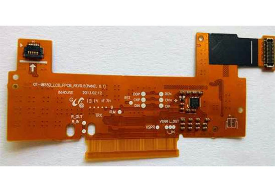
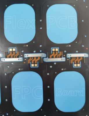
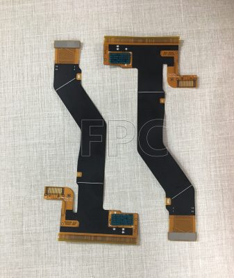
The biggest difference between Flex PCB (FPC) and ordinary FR4 Rigid PCB that lies in its “flexible”. Therefore, the core technology in SMT Assembly is to turn the flex board into a rigid board type. The realization method is to use fixtures and trays as auxiliary to proceed production. Another key point is to ensure that the FPC installation surface is flat.

Factors that cause uneven processing of FPC SMT Assembly
1. Deformation of FPC;
2. The thickness and location of the attached material;
3. The thickness of FPC stiffener or adhesive tape.

Measures to solve the problem of uneven of FPC SMT Assembly
1. High temperature tape is the main factor that affects the surface finish of FPC. In order to be able to eliminate the influence on solder paste printing, it is generally required to carry high-temperature protective tape at a distance of more than 8mm from the pad (depending on the size of the pad and the thickness of the tape).
2. FPC reinforcement board and adhesive are another main factor that affects the flatness of the FPC surface. Generally, it can be solved by using the method of digging grooves on the pallet. The design of FPC should be the distance between the reinforcement board and the back glue to the cushion, such as 8mm.
3. The thickness and opening design size of the magnetic clamping fixture. Generally, 0.06mm thick stainless steel is used. Printing ratio of 6-8m or more.

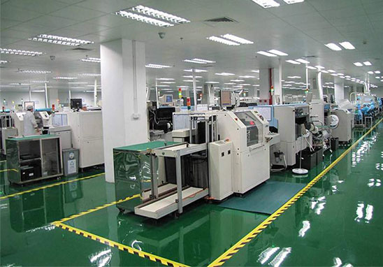
Grande SMT Assembly Capability
1. The largest board: 310mm*410mm (SMT);
2. Maximum board thickness: 3mm;
3. Minimum board thickness: 0.5mm;
4. The smallest Chip components: 0201 package or parts above 0.6mm*0.3mm;
5. The maximum weight of mounted parts: 150 grams;
6. Maximum component height: 25mm;
7. Maximum component size: 150mm*150mm;
8. Minimum lead component spacing: 0.3mm;
9. The smallest spherical component (BGA) spacing: 0.3mm;
10. The smallest spherical part (BGA) diameter: 0.3mm;
11. Maximum component placement accuracy (100QFP): 25um@IPC;
12. Mounting capacity: 3 to 4 million points/day.

